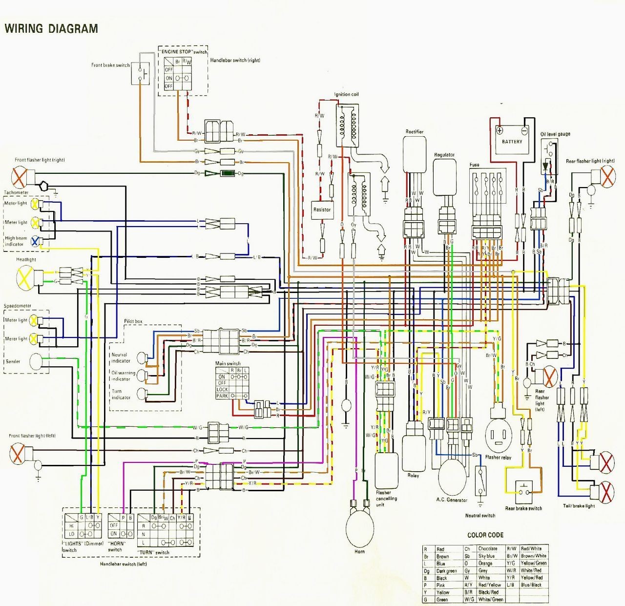
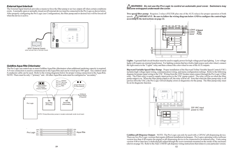
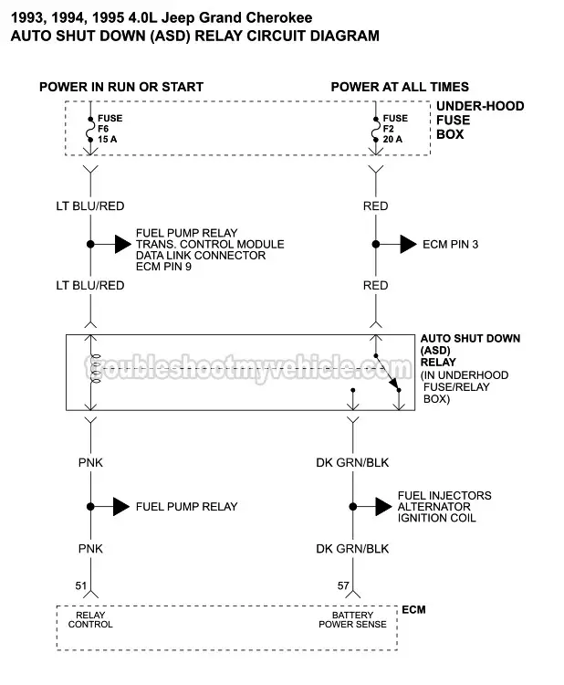
Aqua Logic Wiring Diagram
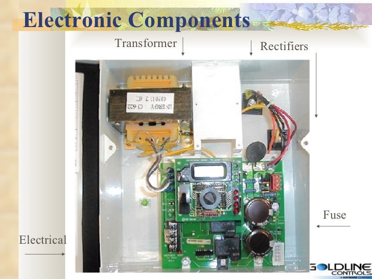
Electrical wiring (page 10) main service grounding and bonding circuit breakers aqua logic control power high voltage pool equipment The aqua logic can control pumps, valves, lighting, heaters, and chlorination.
Hayward Goldline Rectifier Wiring Diagram Wiring
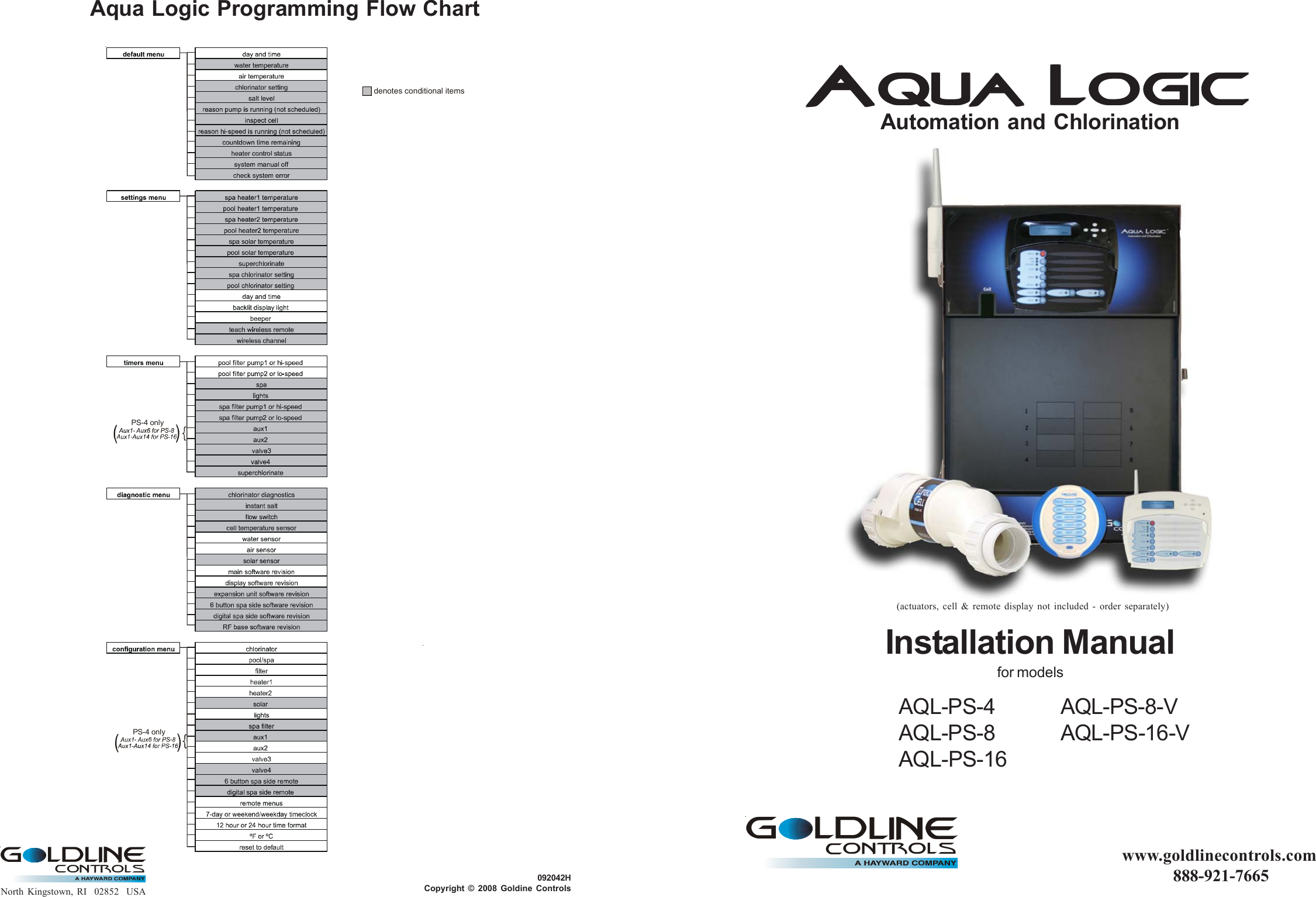
Although the aqua logic is easy to use, it is important to completely read through this operating manual before attempting to operate the control.
Aqua logic wiring diagram. To reduce the risk of electric shock, this terminal must be connected to the grounding means provided in the electric supply service panel with a continuous copper wire equivalent in size to the circuit conductors supplying the equipment. Please note that some of these documents are hayward produced and hayward owned. Although the aqua logic is easy to use, it is important to completely read through this operating manual before attempting to operate the control.
The pureline salt system has a 2 year warranty. Use four conductor cable (typically phone cable) to connect the remote control to the pro logic/aqua logic control center as shown below. Given only a small footprint to work with, they were able to fulfill all our specs.
The aqua logic can control pumps, valves, lighting, heaters, and chlorination. Aqua logic designed and built a complete skid mounted life support system for our sea turtle hospital tanks. Because of the difference in wiring of these earlier boards, the supplied wiring harness must be used.
Display) from the wiring compartment on the pump (fig 19). The aqua logic is designed to be used as a circuit breaker subpanel for all the pool equipment. Although the aqua logic is easy to use, it is important to completely read through this operating manual before attempting to operate the control.
If you opt to purchase the pureline salt system, you will not be able to control it from the aqualogic system. Clicking on the above link will take you to my ebay customer reviews for the. Rov wiring diagrams manual dvx xc trv xt xr prowle r wildcat mud pro.
Refer to the instructions and diagram on page 3 for more information regarding remote mounting. Rev f and earlier aqua logic mainboards: The aqua logic is a multifunction pool controller used to fully manage your pool/spa system.
Aqua logic main unit remote display/keypad (optional) temperature sensors valve actuators (if applicable) 3. Run the electrical service from the house's main panel to the aqua logic. The aqua logic is an automation system that has the salt system built into it.
G flow monitor (flow switch connector) h p transformer input (120vac x 2) Hayward board repair by b&l enterprises. Wire "a" on the pump to 2 on the controller,.
Plumbing (page 8) general pool equipment turbo cell flow switch 4. This page has been created to help you to diagnose your system and rule out problems with specific components of your hayward chlorine generator. If desired, an external subpanel can be used.
Direct mounting on aqua logic control unit disconnect power and then remove the panel from the aqua logic control unit. The aquarium has been using aqua logic products. The maximum wiring distance is 500ft.
Secure the base station in place by firmly tightening the nut from inside of the enclosure. Direct mounting on pro logic or aqua logic control unit disconnect power and then remove the panel from the pro logic or aqua logic control unit. The easiest way to force solar off is to go to the settings menu / pool solar & spa solar and temporarily lower the temperature settings below the current water temperature.
Receiver may have to mounted remotely from the aqua logic control unit in order to achieve reliable communications. Note that the terminals on both the main unit and the remote. The aqua logic can control pumps, valves, lighting, heaters, and chlorination.
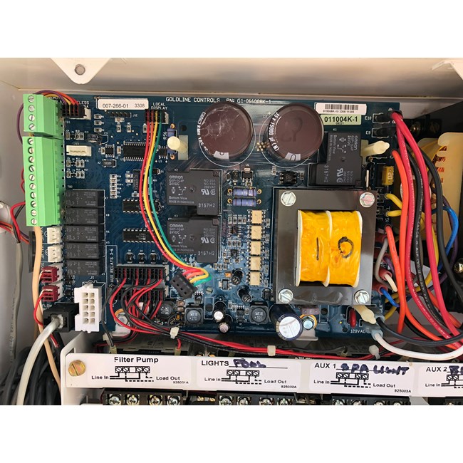
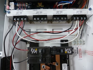
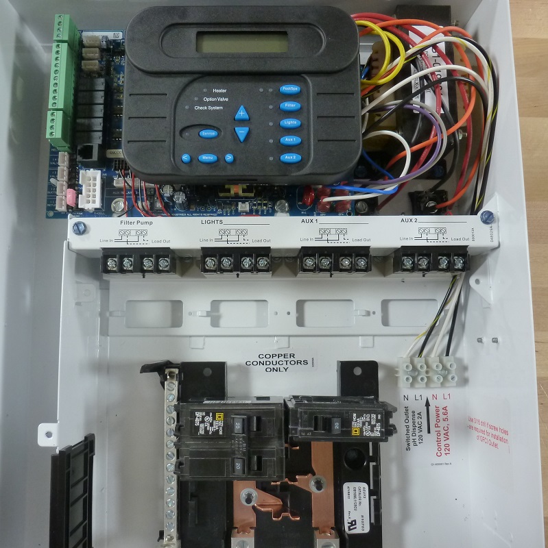
Wiring the pro logic or aqua logic main unit can connect to a maximum of 3 remote display/ keypads. •a green colored terminal marked "grounding" is located inside the wiring compartment. Wire/conduit for 100a service from main panel to aqua logic wire/conduit for filter pump and other high voltage loads wire for bonding miscellaneous utility electrical outlet and weatherproof cover (for mounting on side of aqua logic) mounting hardware (screws, etc.) for mounting aqua logic and remote display/keypad
The aqua logic is a multifunction pool controller used to fully manage your pool/spa system. Then install appropriate circuit breakers and wire the pool equipment through the aqua logic relays.

Hayward Aquarite Change 220 To 110 Wiring Diagram
21 Beautiful 2007 Toyota Camry Stereo Wiring Diagram

Hayward Aquarite Change 220 To 110 Wiring Diagram
[DIAGRAM] Hayward 2 Speed Pool Pump Wiring Diagram FULL
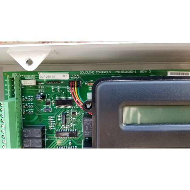
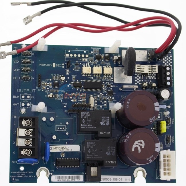
Goldline Controls PCB Circuit Board AquaLogic GLXPCBMAIN

Hayward Aquarite Change 220 To 110 Wiring Diagram
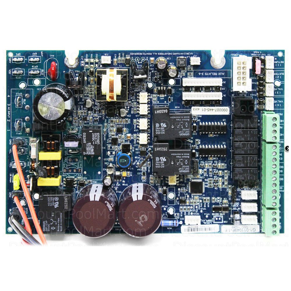
Hayward Pro Logic Main Circuit Board GLXPCBPRO
Hayward Goldline GLXPCBMAIN replacement Main board for

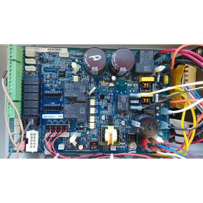
Hayward AquaPlus / ProLogic Main PCB All Date Code
ProLogic Troubleshooting YouTube


Hayward Aqua Rite Wiring Diagram Wiring Diagram
Ryder Bypass Relay Wiring Diagram Irish Connections
How To Wire A 2Speed 230V Motor to a Hayward Pro Logic
Jandy Spa Side Remote Wiring Diagram 11

Hayward Aquarite Change 220 To 110 Wiring Diagram

Wiring with a Variable Speed pump Trouble Free Pool
Hayward Aquarite Change 220 To 110 Wiring Diagram
Goldline Controls PCB Circuit Board AquaLogic GLXPCBMAIN
Goldline Controls Aqua Rite Main PCB (OEM) GLXPCBRITE